Two Stage Gear-Box
Sep 2016 — Dec 2016
Powertrain Systems Design
Team: Amit S , Jinhong Saw
Tools
Matlab
Skills
Gear Design
Shaft Design
Bearing Design
BACKGROUND
System Requirement
A compact and enclosed unit, which is mounted directly to the motor output, is a right angle motor speed reducer - Use helical spur gear for smooth, quiet operation.
Bevel gears will be ‘Zerol’ gears, which can be treated as straight bevel gears for design purposes.
System Parameters: Assumptions & Specifications
Gears and bearings must provide 25,000 hour life
-Shaft should have infinite fatigue life.
Power Rating: 4.5k kW = 6.035 hp
Reliability: 99%
System Safety Factor: 2
Material: Through-hardened Grade 1 Steel; Hardness = 200 HB


ANALYSIS
Helical and Zerol Gear Design
Material for Helical spur gear and Zerol bevel gear was selected to be through-hardened Grade 1 Steel with the hardness value of 200 HB and quality value of 6 – quality value of 6 meaning standard commercial grade gears. This material was chosen due to the bundance of information available through class materials and equation sheets.
Gear teeth number of 12 was chosen for the helical spur gears to reduce the safety factors as much as possible. The smallest teeth count for the helical spur pinion was 12 due to the Lewis Form Factor.
No information on tooth count of below 12 was available. However, even after choosing the least number of
tooth count, the safety factors for the helical spur gears were still considerably higher than 2.
SF,pinion = 15.8; SH,pinion = 2.07; SH,pinion 2 = 4.26
SF,gear = 18.0; SH,gear = 2.12; SH, gear 2 = 4.49
Identical material was chosen for the Zerol bevel gear for the same reason as that of the Helical spur gear – abundance of information. After three rounds of iteration to look for the ideal tooth count of Zerol bevel gears, N = 25 for the bevel gears yielded safety factor of 2.03 for wear, effectively making the
safety factor of the system into 2.03 meeting the design criteria.
Safety factors of Zerol bevel gears with tooth counts of 15 and 20 were lower than 2.
SF = 3.186; SH = 1.43; SH2 = 2.03
Since the gear geometries have now been defined and finalized, shaft material selection was next in line. For the shaft material, AISI-1020 Cold-Drawn was selected instead of SAE 2340 Steel. Both were viable options but the bearing sizes were what determined the material selection.
By using SAE 2340 Steel, system was able to accommodate smaller shaft diameters but bearing bore size to accommodate the given radial load were already bigger than the shaft diameter using the weaker material of the two, which was AISI-1020 Cold-Drawn.

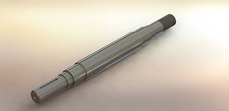
Shaft Design
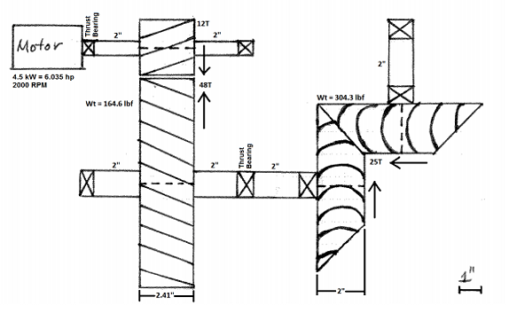
Shaft diameters were calculated to be 0.541 inches for the shaft connected directly to the motor and 0.92 inches for the shaft that connects the spur and the bevel gear. Larger shaft diameter was needed for the lower shaft since the it will have to work with two transmitted loads – one Wt from the spur and the
other Wt from the bevel.


Bearing Design
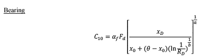
The bearing sizes were then calculated according to the radial loads applied at each bearing locations.
Radial loads on the two bearings on the smaller shaft were identical at 8.7 kN, and since the shaft diameter was 0.54 inches = 13.4 mm, first choice was Ø 2-15mm. However, C10 value for Ø 2-15mm was 7.80 kN, slightly undercutting the 8.7 kN value to achieve factor of safety of 2.
Therefore, next size up Ø 2-17mm was chosen as the appropriate bearing for the upper left shaft.
Moving onto the bearings on the shaft that connects the spur and the bevel – which has a diameter of 0.92 inches = 23.4 mm –, bearing size of Ø 2-25mm had just the right C10 value at 14 kN, which would place the bearing at just above the 12.2 kN value
needed to achieve a factor of safety of 2.